PERCOBAAN 4
RANGKAIAN SUPERPOSISI
Tujuan :
1.
Mahasiswa mampu
memahami rangkaian superposisi.
2.
Mahasiswa mampu
menyelesaikan soal dengan menggunakan teorema superposisi.
3.
Mahasiswa mampu
membandingkan hasil pengukuran dan hasil perhitungan pada rangkaian
superposisi.
4.
Mahasiswa mampu
menganalisa perbandingan hasil pengukuran dan perhitungan pada rangkaian
superposisi.
Dasar Teori :
Teorema
Superposisi memberikan suatu konsep rangkaian yang penting. Dimana tiap sumber
energy dipertimbangkan secara terpisah. Tiap-tiap efek kemudian dikombinasikan
untuk memberikan efek total.
Konsep
ini dapat digunakan untuk anbalisi rangkaian yang sederhana. Beberapa pedoman
pada rangkaian dimana lebih cocok untuk analisis superposisi, yaitu :
1.
Lebih
dari satu sumber energy
2.
Sumber
tegangan atau sumber arus
3.
Struktur
rangkaian sempurna
Ada enam dasar
operasi dalam penerapan teorema superposisi untuk menganalisa rangkaian :
1.
Pilih
satu sumber energy
2.
Untuk
sumber yang lain :
a.
Sumber
tegangan dihubung singkat ( short circuit)
b. Sumber arus di open circuit
b. Sumber arus di open circuit
3.
Hitung
resistansi
4.
Tentukan
arus atau tegangan tiap-tiap elemen. Catat arah dan polaritasnya
5.
Ulangi
langkah 1 sampai 4 untuk sumber yang lain
6.
Jumlahkan
hasil masing-masing secara dialjabarkan
Contoh :
1. Berapa
arus dalam rangkaian gambar di bawah ini?

Penyelesaian
:
·
Sumber
E2 dishort circuit


I3’ =
I1’-I2’ = 4,386mA – 2,632mA = 1,754mA
·
Sumber
E1 dishort circuit
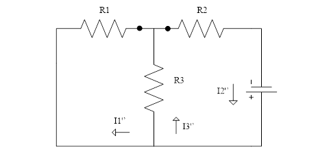

I3’’
= I2’’ – I1’’ = 7,602mA – 5,263mA = 2,339mA
Sehingga
:
I1 =
I1’ + I1’’ = 4,386 + 5,263 = 9,649mA (Ke kanan)
I2 =
I2’ + I2’’ = 2,632 + 7,602 = 10,23mA (Ke kanan)
I3 =
I3’’ - I1’ = 2,339 – 1,754 = 0,585mA (Ke
atas)
2. Hitung
arus dalam rangkaian di bawah ini.

Penyelesaian
:
·
Sumber
arus ( I ) open circuit


I3’
= I4’ = I1’ – I2’ = 0,6 – 0,4 = 0,2mA
·
Sumber
tegangan dishort circuit


Arus Total :
I1 = I1’ – I1’’
= 0,6 – 0,2 = 0,4A
I2 = I2’ + I2’’
= 0,4 + 0,2 = 0,6A
I3 = I3’’ – I3’
= 0,4 – 0,2 = 0,2A
I4 = I4’ – I4’’
= 0,2 + 0,6 = 0,8A
Daftar Alat dan Bahan :
1.
Multimeter
2.
Konektor
3.
Power supply
4.
Resistor:
100
Ω 3
buah
330
Ω 2
buah
560
Ω 1 buah
150
Ω 2 buah
47 Ω 2 buah
Prosedur Percobaan :
1. Gambar rangkaian

Langkah percobaan :
1. Buatlah
rangkaian seperti gambar a.
2.
Ukurlah arus dan
tegangan pada setiap hambatan pada rangkaian a.
3.
Hitung arus pada saat V1
di short circuit.
4.
Hitung arus pada saat V2
di short circuit.
6.
Setelah mendapatkan
hasil perhitungan arus pada setiap hambatan, maka carilah nilai tegangan yang
mengalir pada setiap hambatan.
7.
Bandingkan hasil
pengukuran dan perhitungan.
2. Gambar Rangkaian
 |
Langkah
percobaan :
1. Buatlah
rangkaian seperti gambar b.
2.
Ukurlah arus pada
setiap hambatan pada rangkaian b.
3.
Pilih salah satu sumber
energi.
4.
Pada saat sumber tegangan aktif dan sumber arus off (di
open circuit), hitung arus yang mengalir pada setiap
resistor.
5.
Pada
saat sumber arus aktif dan sumber tegangan off (short circuit),
hitung arus
pada setiap resistor menggunakan
pembagi arus.
6.
Jumlahkan secara
aljabar arus pada setiap hambatan yang
telah dicari.
7. Bandingkan
hasil pengukuran dan perhitungan.
3. Gambar rangkaian

Langkah
Percobaan :
1. Buatlah
rangkaian seperti gambar c.
2.
Ukurlah arus dan
tegangan pada setiap hambatan pada rangkaian c.
3.
Sumber arus di open circuit,
hitung arus yang mengalir pada setiap resistor.
4.
Sumber tegangan di
short circuit, hitung arus yang mengalir pada setiap resistor.
5. Jumlahkan
secara aljabar arus pada setiap hambatan
yang telah dicari.
6.
Setelah mendapatkan
hasil perhitungan arus pada setiap hambatan, maka carilah nilai tegangan yang
mengalir pada setiap hambatan.
7. Bandingkan
hasil pengukuran dan perhitungan.
4. Gambar rangkaian

Langkah
Percobaan :
1. Buatlah
rangkaian seperti gambar d.
2. Ukurlah
arus pada setiap hambatan pada rangkaian d.
3.
Pilih satu sumber
sumber tegangan.
4.
Sumber tegangan
dihubungkan singkat (short ciruit), hitung hambatan yang mengalir pada setiap
resistor.
5.
Ulangi langkah 3-4
untuk sumber tegangan yang lain.
6.
Jumlahkan secara
aljabar arus pada setiap hambatan yang
telah dicari.
7.
Bandingkan hasil
pengukuran dan perhitungan.
5. Gambar rangkaian

Langkah
Percobaan :
1. Buatlah
rangkaian seperti gambar e.
2. Ukurlah
arus pada setiap hambatan pada rangkaian e.
3.
Pilih satu sumber
tegangan.
4.
Sumber tegangan
dihubungkan singkat (short circuit), hitung hambatan yang mengalir pada setiap
resistor.
5.
Ulangi langkah 3-4 untuk
sumber tegangan yang lain.
6.
Jumlahkan secara
aljabar arus pada setiap hambatan yang
telah dicari.
7. Bandingkan
hasil pengukuran dan perhitungan.


